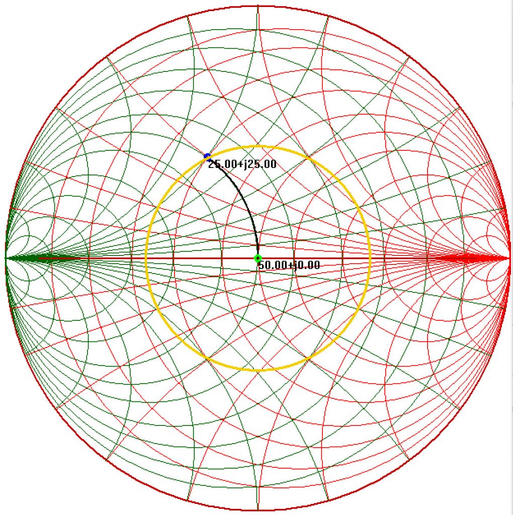
Many circuits have elements connected in parallel that are a natural fit for the “Acceptance” quantity of Admittance (Y) and its constituent quantities of Conductance (G) and susceptance (B), where Y=G+jB. (B=ωC for a capacitor, and B=1/ωL for an inductor.) Y=1/Z=1/(R+jX), so that G=1/R only if X=0, and B=-1/X only if R=0.
The most common orientation of the Smith chart places the resistance axis horizontally with the Short Circuit (SC) location at the far left. There’s a good reason for this: the voltage of the reflected wave at a Short Circuit must cancel the voltage of the incident wave so that zero potential exists across the short circuit. In other words, the voltage reflection coefficient must be -1 or a magnitude of 1 at an angle of 180 degrees. Since angles are measured from the positive real axis and the real axis is horizontal, the short circuit location and horizontal orientation make sense.

